Door alarms have gotten more sophisticated over the years, but many newer systems are proprietary or comparatively expensive, especially when using Zigbee or similar ecosystems. The older 433 MHz sensors are cheap, simple, and widely available. Most of them use fixed-code amplitude encoding (1527, typically based on the EV1527 chip). The downside is range. In practice, the signal quality from these devices and the common receivers sold online can be poor. If the distance is more than a short span, something has to relay the signal.
Enter LoRa
LoRa is a low-power, long-range radio technology intended for small telemetry-style messages. Even with a basic wire antenna, it can easily cover distances on the order of a mile. Development boards are also reasonably priced, usually around $30, which makes them practical for small projects.
The Problems
I have a shed roughly 100 yards from the house and wanted to add a door alarm. My first approach used two LoRa boards: one mounted at the shed with a reed switch, and one in the house connected to a buzzer.
The shed has two double doors that secure two separate sections. Running another reed switch to cover the second door is easy enough, but there is also a smaller shed on the property without power. That meant I needed a battery-powered wireless solution. At that point, using additional LoRa boards started to feel like overkill compared to just using off-the-shelf door sensors.
A simpler idea was to install common 433 MHz door sensors (and a couple of smoke detectors that use the same 1527 encoding) and set up a single receiver in the house. That would eliminate the need for multiple LoRa nodes entirely.
On paper, this seemed like the cleanest approach. In practice, the wireless range was abysmal and couldn’t reliably reach the house. See here
The Solution
I’ll use the LoRa transmitter in the shed as a forwarder to the house and just change the receiver’s firmware. The flow will look like this:
Hardware
- Boards
- Adafruit Feather RF96 M0
- This can be swapped for an ESP board with an RF96 chip but the pin numbers may differ. This ARM chip doesn’t have as large of a library compared to the ESP boards.
- Antenna: 8.2cm length of wire
- 433MHz: RXB6 Receiver
- Other receivers have terrible sensitivity or are packet-based. Do not use them.
- Antenna: 17.32cm length of wire
- Adafruit Feather RF96 M0
- Sensors:
- Generic 433MHz sensor supporting 1527
- Generic reed switch(optional)
- Cases(3D printed):
- Found on Thingiverse.
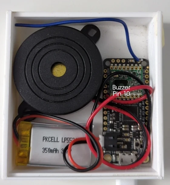
- Buzzer
- Any 3.3V buzzer large enough to hear across the house.
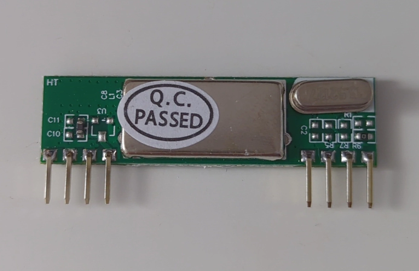 The RXB6 receiver.
Wiring
The RXB6 can be powered from 3.3V. If you power it from 5V, the data pin can still be connected directly to a microcontroller input, as the output signal does not exceed 3.3V. In my testing it typically stayed around ~1.2V.
The 912 MHz antenna connects to the small antenna via pad at the top-right of the Feather board.
If you are using the two reed (magnetic) switch inputs, you can either place a low-value resistor inline or enable the internal pull-up resistors. The code below uses the internal pull-ups, which simplifies the wiring.
Pin mapping can be inferred directly from the code, or from the photos below.
Forwarder
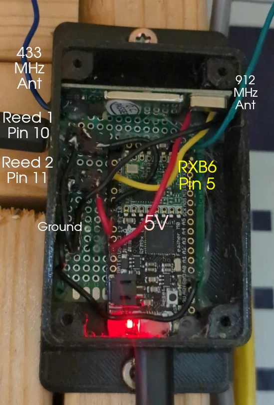
Note: The 912 MHz antenna can be pointed downward. On my build, I expanded the ground across the protoboard to make it easier to connect all devices. This is not necessary if you are only using the RXB6.
Receiver
Firmware
I used the Arduino IDE with the RCSwitch, SPI, and RadioHead libraries, all available through the Library Manager.
The Adafruit Feather M0 needs a board repository added: https://adafruit.github.io/arduino-board-index/package_adafruit_index.json This can be added under Preferences → Additional Boards Manager URLs.
Flashing the forwarder
After wiring the forwarder, flash it using the code from: https://github.com/Daniel-McDonough/433mhz-to-lora-forwarder
Leave it connected to the computer and open the serial monitor. Activate each 433 MHz device you plan to use and note the codes that appear in the output. These will be added to the receiver firmware.
Flashing the Receiver
Use the receiver code from the same repository and add your captured 1527 codes to the lists shown below, replacing the existing values.
For the door sensors: const long triggerCodes[] = {10000001, 10000002, 00000000, 00000001, 00000002, 00000003}
Keep 10000001 and 10000002 if you are using the two reed switch inputs on the forwarder.
For smoke detectors or other alarms: const long smokeDetectorCodes[] = {20000000, 20000002};
Flash the receiver board the same way as the forwarder, then test by activating one of the sensors.
Troubleshooting
Check the logs from the forwarder in the serial monitor to make sure it’s receiving, processing, and forwarding the codes.
Make sure the antennas are fairly straight and in the same orientation.
Activate the sensor from a closer distance(~2 feet).
Distance the boards from one another.
Make sure your sensors use 1527 encoding.
Failures
The type of 433 MHz receiver board matters more than expected. The MX-RM-5V has very poor reception, even when paired with a longer antenna. There are modifications floating around that claim to improve sensitivity, but they are not worth the effort.
I spent a lot of time trying to improve range before eventually finding a comparison chart that showed just how much performance varies between these modules. Most of the commonly sold boards perform badly. The RXB6 superheterodyne receiver is the clear exception.
After switching to the RXB6, I accidentally triggered a door sensor while inside the house and the buzzer went off. At that point it became clear that the forwarder setup wasn’t strictly necessary after all.
With the RXB6 and a properly sized antenna, the shed is just within range from the house. It works, but it’s right on the edge. The current LoRa-based setup is likely more reliable overall since the protocol is more robust and the two LoRa devices are operating well within their usable distance.
Security Considerations
There is an inherent security limitation with this approach that can’t really be addressed without switching to more secure sensors. Since the system relies on fixed 1527 codes, anyone who knows or captures those codes could repeatedly transmit them and trigger the alarm.
The forwarder also blindly relays any valid-looking code it receives. In the worst case, this could be abused to repeatedly trigger alerts or effectively create a denial-of-service situation by spamming transmissions.
A basic mitigation would be to add a whitelist on the forwarder so it only relays known device codes. However, that means capturing and hardcoding all codes in both the forwarder and receiver firmware, and reflashing whenever a new device is added.
LoRa itself can be secured, which may be worth doing later if more LoRa nodes are added for things like ATV, tractor, or camper tracking/alerts. Right now, the sensors remain the weakest link.
Future Projects
Connecting the Setup to HomeAssistant
Integrating this with HomeAssistant should be fairly straightforward by pushing received codes to MQTT over WiFi. The door sensors also transmit close events, so it would be possible to track both open and close states. I would need to decide where that logic should live (forwarder vs. receiver vs. HomeAssistant itself).
ESPHome does have some support for capturing 433 MHz signals directly, which could eliminate parts of this setup. However, the documentation is sparse and support appears to vary depending on the specific receiver hardware.
Tracking Other Objects
Because of LoRa’s range, it would be easy to place additional boards in ATVs or the tractor and have them transmit events when powered on or when movement is detected. GPS data could also be included.
When tied into HomeAssistant, this could be used for notifications or simple presence tracking through the mobile app.
Make a Repeater
Another option would be to add a 433 MHz transmitter to the receiver board and retransmit any LoRa-received codes back onto 433 MHz.
This could be useful for extending the range of an existing security system that already relies on the same type of sensors.
The code is below but the Github repo is likely more up to date.
The forwarder code:
#include <RCSwitch.h>
#include <RH_RF95.h>
#include <SPI.h>


#define RXB6_RX_PIN   5   // RX pin for RXB6 - Adjust this pin as per your wiring
#define RF95_CS      8   // Chip select pin for RF96
#define RF95_RST     4   // Reset pin for RF96
#define RF95_INT     3
#define TRIGGER_PIN1 10  // Trigger pin 1
#define TRIGGER_PIN2 11  // Trigger pin 2

// Instantiate the RF95 (RF96) and RCSwitch objects
RH_RF95 rf95(RF95_CS, RF95_INT);
RCSwitch rcSwitch = RCSwitch();

unsigned long lastReceivedTime = 0;  // Last received time for debounce
long lastReceivedCode = -1;          // Last received code for debounce
const unsigned long debounceTime = 3000;
bool PIN1_RESET = false;
bool PIN2_RESET = false;

void setup() {
    Serial.begin(9600);

    // Initialize RCSwitch for receiving 1527 encoded messages
    rcSwitch.enableReceive(digitalPinToInterrupt(RXB6_RX_PIN)); // Enable receiver on interrupt

    // Manual reset of RF96 to make sure it's initialized
    pinMode(RF95_RST, OUTPUT);
    digitalWrite(RF95_RST, HIGH);
    delay(100);
    digitalWrite(RF95_RST, LOW);
    delay(100);
    digitalWrite(RF95_RST, HIGH);
    delay(100);

    // Initialize RF95 (RF96) module
    if (!rf95.init()) {
        Serial.println("RF96 initialization failed!");
    }

    // Set the frequency for the RF96 module
    if (!rf95.setFrequency(915.0)) {
        Serial.println("Setting RF96 frequency failed!");
    } else {
        Serial.println("RF96 frequency set to 915.0 MHz");
    }

    // Initialize trigger pins
    pinMode(TRIGGER_PIN1, INPUT_PULLUP);
    pinMode(TRIGGER_PIN2, INPUT_PULLUP);
}

void loop() {
    // Check for external triggers
    checkExternalTriggers();

    // Check if RCSwitch has received a message
    if (rcSwitch.available()) {
        long receivedValue = rcSwitch.getReceivedValue();

        // Check if the code is a duplicate and if it's within the debounce time
        if (receivedValue == lastReceivedCode && millis() - lastReceivedTime < debounceTime) {
            rcSwitch.resetAvailable();
            return;
        }

        // Update the last received code and time
        lastReceivedCode = receivedValue;
        lastReceivedTime = millis();

        // Process the received code
        processReceivedCode(receivedValue);
        rcSwitch.resetAvailable();
    }
}

//Checks the two reed switches connected to the board and debounces them
//Reset logic added to stop

void checkExternalTriggers() {

    if (digitalRead(TRIGGER_PIN1) == HIGH && !PIN1_RESET) {
        //Send code for receiver to process
        processReceivedCode(10000001);
        //Debounce
        delay(300);
        PIN1_RESET = true;
    }
    if (digitalRead(TRIGGER_PIN1) == LOW && PIN1_RESET) {
        delay(300);
        Serial.println("1 closed");
        PIN1_RESET = false;
    }
    if (digitalRead(TRIGGER_PIN2) == HIGH && !PIN2_RESET) {
        //Send code for receiver to process
        processReceivedCode(10000002);
        delay(300);
        PIN2_RESET = true;
    }
    if (digitalRead(TRIGGER_PIN2) == LOW && PIN2_RESET) {
        delay(300);
        Serial.println("2 closed");
        PIN2_RESET = false;
    }

}

void processReceivedCode(long receivedValue) {
    if (receivedValue > 0) {
        Serial.print("Received: ");
        Serial.println(receivedValue, DEC);

        // Prepare a buffer to send the message
        uint8_t buf[sizeof(receivedValue)];
        memcpy(buf, &receivedValue, sizeof(receivedValue));

        // Send the message via RF96
        if (rf95.send(buf, sizeof(buf))) {
            rf95.waitPacketSent();
            Serial.println("Message forwarded via RF96");
            } else {
                Serial.println("Error sending message via RF96");
            }
            } else {
               Serial.println("Received unknown code");
            }
}
The LoRa receiver code:
#include <RH_RF95.h>

#define RF95_CS      8   // Chip select pin for RF96
#define RF95_RST     4   // Reset pin for RF96
#define RF95_INT     3   // Interrupt pin for RF96
#define BUZZER_PIN   10  // Buzzer pin
#define LED_PIN      13

// Door codes
const long triggerCodes[] = {10000001, 10000002, 00000000, 00000001, 00000002, 00000003}; // Add your standard codes here
const int numTriggerCodes = sizeof(triggerCodes) / sizeof(triggerCodes[0]);

// Smoke detector codes
const long smokeDetectorCodes[] = {20000000, 20000002}; // Replace with actual smoke detector codes
const int numSmokeDetectorCodes = sizeof(smokeDetectorCodes) / sizeof(smokeDetectorCodes[0]);

RH_RF95 rf95(RF95_CS, RF95_INT);

void setup() {
    pinMode(RF95_RST, OUTPUT);
    digitalWrite(RF95_RST, HIGH);
    pinMode(BUZZER_PIN, OUTPUT);
    pinMode(LED_PIN, OUTPUT);

    if (!rf95.init()) {
        // If init fails, blink LED rapidly
        while (1) {
            digitalWrite(LED_PIN, HIGH);
            delay(100);
            digitalWrite(LED_PIN, LOW);
            delay(100);
        }
    }
    if (!rf95.setFrequency(915.0)) {
        // If frequency set fails, blink LED slowly
        while (1) {
            digitalWrite(LED_PIN, HIGH);
            delay(1000);
            digitalWrite(LED_PIN, LOW);
            delay(1000);
        }
    }
    // If setup is successful, turn on LED for 2 seconds
    digitalWrite(LED_PIN, HIGH);
    delay(2000);
    digitalWrite(LED_PIN, LOW);
}

void loop() {
    if (rf95.available()) {
        uint8_t buf[RH_RF95_MAX_MESSAGE_LEN];
        uint8_t len = sizeof(buf);

        if (rf95.recv(buf, &len)) {
            if (len == sizeof(long)) {
                long receivedCode;
                memcpy(&receivedCode, buf, len);

                if (processReceivedCode(receivedCode)) {
                    // Turn on LED to indicate code processed
                    digitalWrite(LED_PIN, HIGH);
                    delay(500);
                    digitalWrite(LED_PIN, LOW);
                }
            }
        }
    }
}
//Determine which function to call based on door or smoke detector
bool processReceivedCode(long code) {
    for (int i = 0; i < numSmokeDetectorCodes; i++) {
        if (code == smokeDetectorCodes[i]) {
            smokeDetectorAlert();
            return true;
        }
    }

    for (int i = 0; i < numTriggerCodes; i++) {
        if (code == triggerCodes[i]) {
            beep(3);
            return true;
        }
    }
    return false;
}

// Change the timings and count to your liking
void beep(int numOfBeeps) {
    for (int i = 0; i < numOfBeeps; i++) {
        digitalWrite(BUZZER_PIN, HIGH);
        delay(300);
        digitalWrite(BUZZER_PIN, LOW);
        if (i < numOfBeeps - 1) {
            delay(300);
        }
    }
}

void smokeDetectorAlert() {
    for (int i = 0; i < 10; i++) {
        digitalWrite(BUZZER_PIN, HIGH);
        delay(1000);
        digitalWrite(BUZZER_PIN, LOW);
        delay(100);

        for (int i = 0; i < 3; i++) {
            digitalWrite(BUZZER_PIN, HIGH);
            delay(300);
            digitalWrite(BUZZER_PIN, LOW);
            delay(100);
        }
    }
}