This post originally published on github.
This ESPHome configuration has been tested with an older ~2017 Haiku fan using an IR blaster board using an ESP8285.
The ESP8285 IR boad was purchased from Aliexpress.
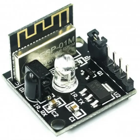
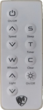
This is the remote used to record the IR commands. It may work with other Big Ass Fans brand fans that support IR control. IR codes for all buttons are in ir-codes.txt.
Hardware
Flashing:
- TTL or FTDI cable
- 5v power source
Install:
- 5v power source
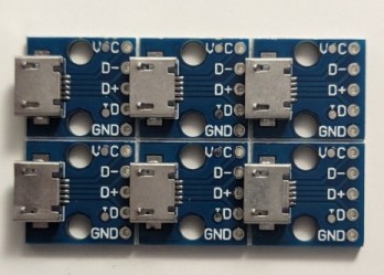
- (Optional) USB micro/C board to power via USB
- (Optional) Solder equipment
- (Optional) 3D Printed case
Installing
Requirements:
- Homeassistant server
- 2.4GHz Wi-Fi
- TTL/FTDI cable
- Computer capable of installing esptool
ESPHome:
You need to install ESPHome via the getting started guide if using Hassio. If not using Hassio, you will add the board later.
FTDI Cable:
Wire the FTDI cable accordingly to the board. The board uses 5v power so you don’t need any logic or voltage shifters.
Install Esphome Terminal Software:
Follow the install instructions on the esphome wiki.
Flashing:
Fill in the ssid and password entries in the ir.yaml file. You an optionally fill in the OTA password for subsequent updates over the air and/or an API password.
Flash the ESP8285 board using the first uploading instructions. Be sure to specify ir.yaml.
esphome run ir.yaml
After a successful flashing, the logging output will be displayed. Note the obtained IP address if not using the ESPhome Hassio addon.
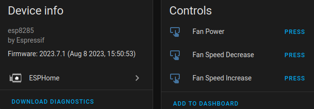
Add to HomeAssistant:
In HomeAssistant, add the ESPHome integration. Fill in the IP address and API password(if any) and the board should now be added to HomeAssistant. You will see the buttons available on the device info page.
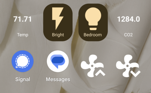
You can then add these buttons to the HomeAssistant dashboard. They are prefixed with “button.”. You an optionally add them to your phone’s homescreen if the HomeAssistant app is installed.
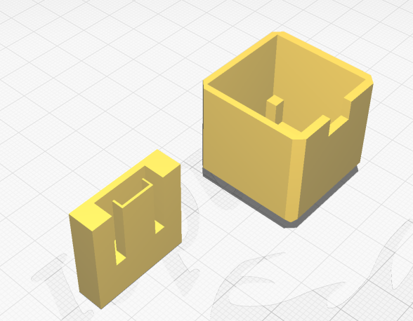
Case:
Requirements:
- FDM printer
- PLA filament
- Micro-USB board (13mm x 14mm)
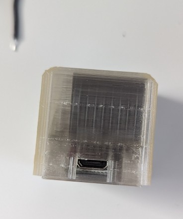
The case allows for one to power the board via micro-USB. The micro-USB board was purchased off Aliexpress and is 13mm wide and 14mm deep.
Print the top piece upside down with supports and all walls(walls = 999). If you use infill, the top of the case will not look as pretty. Print the bottom piece with the micro USB port facing up.
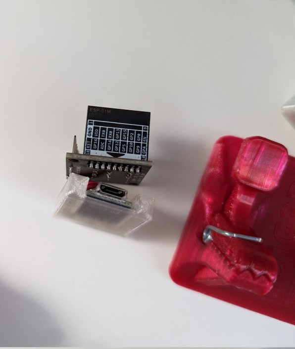
Assembly
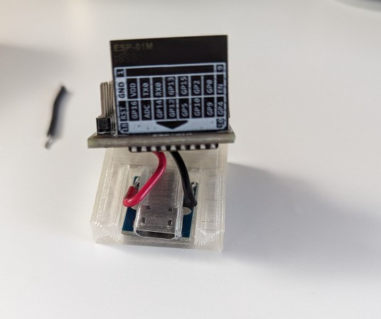
Solder the 5V and ground to the top of the USB micro board and to the bottom of the IR board. Gently slide the USB micro board into the bottom piece. Be careful not to break the USB port cover as it prevents shorting on the IR board.
Insert the IR board into the top housing with the ESP board side facing the notch. The posts inside will keep the board level.
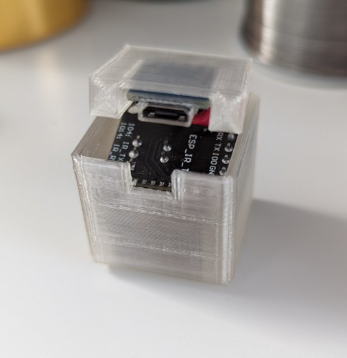
Gently press the bottom piece into the top housing.
The device should be good to go. Plug it into any 5v USB source.